Essential Shear Force And Bending Moment Diagrams For Structural Design
Shear force and bending moment diagrams are essential tools for structural engineers to design safe and efficient structures. To draw these diagrams, one must understand the concepts of shear force and bending moment, which describe the forces and moments acting on a beam. Equilibrium equations and the method of sections are used to calculate these values at specific points. The step-by-step process involves cutting an imaginary section through the beam and analyzing the forces and moments at that point. By connecting these points, engineers can draw the diagrams, which provide valuable insights into the structural behavior of a beam, helping them determine critical points for design.
The Vital Importance of Understanding Shear Force and Bending Moment Diagrams in Structural Design
When it comes to ensuring the integrity and stability of structures, architects, engineers, and contractors rely heavily on shear force and bending moment diagrams. These diagrams provide crucial insights into the internal forces acting on structural elements, helping designers optimize their designs for strength and safety. Without a thorough understanding of these diagrams, structural design can become a perilous endeavor.
The Significance of Shear Force and Bending Moment Diagrams
Shear force is the force that tends to cause a beam to slide or tear apart, while bending moment is the force that tends to cause it to bend or buckle. By analyzing shear force and bending moment diagrams, engineers can:
- Identify critical points where structural elements are most susceptible to failure
- Determine the required strength of beams, columns, and other structural members
- Optimize material usage and reduce costs by identifying areas where excess strength is not necessary
- Ensure the overall safety and durability of the structure
Understanding the Basics
Understanding shear force and bending moment diagrams begins with defining each concept:
- Shear force is the algebraic sum of all forces acting perpendicular to the axis of the beam.
- Bending moment is the algebraic sum of all moments acting on the beam’s cross-section.
Various types of forces can contribute to shear force and bending moment, including concentrated loads, distributed loads, and moments.
Understanding the Basics of Shear Force and Bending Moment
In the realm of structural design, the complexity of forces acting upon structures demands a profound understanding of shear force and bending moment. These concepts are fundamental to ensuring the integrity and stability of any structure, from towering skyscrapers to humble bridges.
Shear force represents the force that tends to cause a horizontal sliding or tearing of a structural member. Think of it as a force that tries to slice the member apart. On the other hand, bending moment is the force that causes a curvature or bending of a structural member. Imagine a force that tries to bend the member like a curved rod.
Understanding the types of forces that can induce shear force and bending moment is crucial. These forces can arise from various sources, including:
- Concentrated loads: These are forces that act at specific points, such as the weight of a heavy object resting on a beam.
- Distributed loads: These are forces that are distributed evenly over a surface, like the weight of a roof or a floor.
- Moments: These are forces that cause a rotational effect, such as the torque applied to a bolt.
By grasping the nature of these forces, engineers can accurately determine the shear force and bending moment that will act upon a structure. This knowledge forms the foundation for ensuring that structures can withstand the demands of everyday use and environmental factors, ensuring the safety of those who rely on them.
Determining Shear Force and Bending Moment: The Bedrock of Structural Stability
Equilibrium Equations: The Balancing Act
Shear force and bending moment are crucial parameters for understanding the behavior of structures under external loading. These forces represent the equilibrating forces that balance the external loads acting on a beam or similar structural element.
The equilibrium equations are the mathematical tools we use to determine these forces. For a beam in equilibrium, the sum of vertical forces acting on it must be zero (i.e., the upward forces must equal the downward forces). Similarly, the sum of moments about any point must also be equal to zero.
Sign Conventions: Setting the Stage
Before we delve into the calculations, it’s essential to establish the sign conventions for shear force and bending moment. By convention:
- Shear Force: Positive when acting upward and negative when acting downward.
- Bending Moment: Positive when causing concave upward bending and negative when causing concave downward bending.
These conventions help us interpret the diagrams correctly and identify regions of the beam where the forces are acting in different directions.
Step-by-Step Calculation Process
- Identify the External Loads: Determine the external forces acting on the beam, including concentrated loads (e.g., point loads) and distributed loads (e.g., uniform load over a length).
- Calculate Reactions: Determine the reactions at the supports of the beam, which represent the forces that counteract the external loads.
- Section Cut: Choose a section along the beam where you want to determine the shear force or bending moment.
- Free Body Diagram: Draw a free body diagram of the cut section, showing all the forces acting on it, including the reactions, external loads, and the internal shear force and bending moment.
- Equilibrium Equations: Apply the vertical equilibrium equation to determine the shear force at the cut section. Next, apply the moment equilibrium equation to calculate the bending moment at the cut section.
Grasping the equilibrium equations and sign conventions is paramount for accurately calculating shear force and bending moment diagrams. These diagrams provide a comprehensive understanding of the forces acting on structural elements and are essential tools for ensuring the stability and safety of structures.
The Method of Sections: Unraveling Shear Force and Bending Moment
In the world of structural design, shear force and bending moment are the unsung heroes that ensure the integrity of our buildings and bridges. These diagrams provide a visual representation of the forces acting on a structural element, enabling engineers to make informed decisions about its design.
The method of sections is a technique commonly employed to determine the shear force and bending moment at specific points along a beam. This approach involves cutting an imaginary section through the beam, isolating the section of interest, and then applying the equilibrium equations to determine the forces acting on that section.
The sign conventions for shear force and bending moment must be carefully considered. Positive shear force indicates upward or rightward forces, while negative shear force signifies downward or leftward forces. Positive bending moment indicates a downward force on the right-hand side of the section, and vice versa.
Applying the Equilibrium Equations
The equilibrium equations, which govern the balance of forces and moments acting on a body, are crucial in the method of sections. By summing the forces and moments acting on the isolated section, we can determine the shear force and bending moment at the cut point.
Visualizing Shear Force and Bending Moment
Once the shear force and bending moment at various points along the beam have been calculated, they can be plotted on a graph to create shear force and bending moment diagrams. These diagrams provide a clear visualization of how these forces vary along the length of the beam, allowing engineers to identify critical sections where the beam is most susceptible to failure.
Practical Applications
Shear force and bending moment diagrams are indispensable tools in structural engineering. They are used to:
- Design beams and columns to withstand the forces acting on them
- Identify points of potential failure, enabling measures to be taken to reinforce the structure
- Analyze the behavior of structures under different loading conditions
- Ensure the safety and durability of our built environment
By harnessing the method of sections, engineers can accurately determine shear force and bending moment, paving the way for the development of robust and reliable structures.
Related Concepts
Points of Inflection
Points of inflection are locations where the bending moment changes sign. At these points, the beam transitions from concave to convex, or vice versa. They indicate where the beam switches from bending in one direction to bending in the opposite direction. Points of inflection are crucial for understanding beam behavior and identifying areas of maximum stress.
Maximum Shear Force and Maximum Bending Moment
Maximum shear force and maximum bending moment are critical values for structural design. The maximum shear force represents the highest shear stress experienced by the beam, while the maximum bending moment corresponds to the highest bending stress. These values determine the beam’s strength and capacity to withstand external loads.
Effects of Distributed and Concentrated Loads
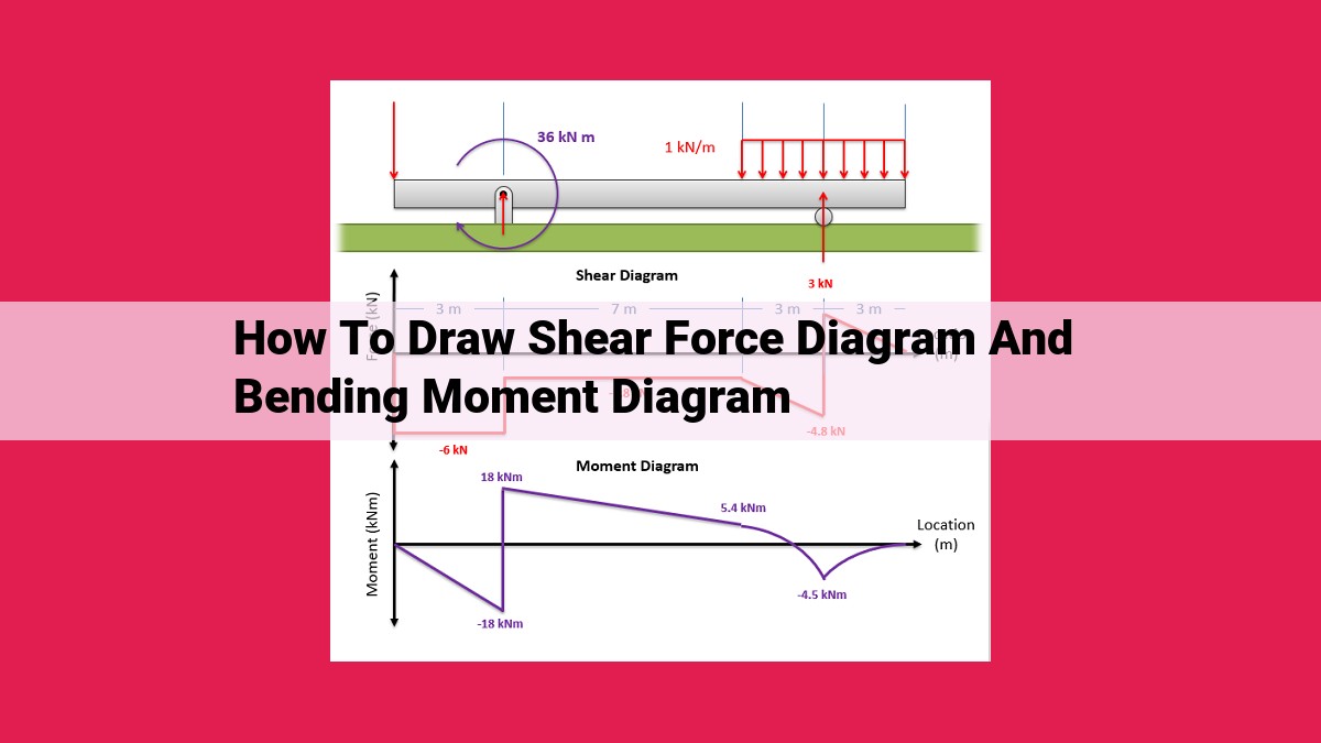
The type of loading has a substantial impact on shear force and bending moment diagrams. Distributed loads, such as those due to self-weight or snow, result in uniform loading across the beam’s length, creating a parabolic shear force diagram and a linear bending moment diagram. In contrast, concentrated loads, such as point loads or line loads, generate abrupt changes in shear force and bending moment, leading to a more complex diagram shape.
Understanding the Story
Imagine a beam supporting a distributed load, like a snowpack on a roof. As the load increases, the beam bends downward, creating a negative bending moment. However, as we move away from the center of the beam, the bending moment gradually reduces until it reaches zero at the points of inflection. Beyond these points, the bending moment becomes positive, indicating that the beam is now bending in the opposite direction.
Similarly, when a concentrated load is applied, it creates a sudden spike in shear force at the point of application. This shear force then gradually decreases as we move away from the load, resulting in a triangular shear force diagram. The bending moment diagram under a concentrated load resembles the shape of a parabola.
By understanding these related concepts, engineers can effectively analyze and design structural members to withstand various loads and ensure their safety and stability.
Drawing Shear Force and Bending Moment Diagrams: A Step-by-Step Guide
Understanding shear force and bending moment diagrams is essential for structural engineers to assess and design safe and efficient structures. These diagrams provide indispensable information about the internal forces acting on a beam or structure, allowing engineers to determine critical points and ensure structural integrity.
To draw a shear force and bending moment diagram, the method of sections is commonly used. This step-by-step approach involves:
Step 1: Determine Reactions at Supports
Calculate the reactions at the supports of the beam using equilibrium equations. These reactions represent the external forces acting on the beam.
Step 2: Cut the Beam at a Section
Imagine cutting the beam perpendicular to its length at a specific point of interest. This creates two free bodies: the left-hand side and the right-hand side.
Step 3: Apply Equilibrium Equations to Free Bodies
For each free body, apply the equilibrium equations to determine the shear force and bending moment at the cut section.
Step 4: Draw the Shear Force Diagram
Start from one end of the beam and plot the shear force calculated at each section. Draw a graph representing the variation of shear force along the beam.
Step 5: Draw the Bending Moment Diagram
Similarly, plot the bending moment calculated at each section and draw a graph representing its variation along the beam.
Tip: Remember the sign conventions for shear force and bending moment. Positive shear force causes clockwise rotation, while positive bending moment causes upward concavity.
By following these steps, engineers can generate shear force and bending moment diagrams that provide crucial insights into the structural behavior of the beam. These diagrams are essential for identifying points of inflection, maximum shear force, and maximum bending moment, which are critical factors in structural design.
Applications of Shear Force and Bending Moment Diagrams
In the realm of structural engineering, shear force and bending moment diagrams are indispensable tools that provide crucial insights into the behavior of structural elements under various loading conditions. These diagrams play a pivotal role in ensuring the safety and integrity of structures, from towering skyscrapers to intricate bridges and everything in between.
Shear force diagrams reveal the distribution of internal forces that act parallel to the cross-section of a structural member, indicating the tendency for the member to slide or shear apart. These diagrams are essential for identifying points of maximum shear stress, which helps engineers determine the appropriate cross-sectional dimensions to resist these forces.
Bending moment diagrams depict the distribution of internal forces that cause a structural member to bend. They indicate the tendency for the member to rotate about an axis perpendicular to its cross-section. By studying bending moment diagrams, engineers can identify points of maximum bending stress, ensuring that the member’s strength is adequate to withstand these forces without failing.
The practical applications of shear force and bending moment diagrams extend far beyond theoretical analysis. They form the foundation for several critical aspects of structural design:
- Member Selection: Diagrams help engineers select appropriate structural members with the right dimensions and material properties to resist the anticipated shear and bending forces.
- Connection Design: They aid in designing load-bearing connections that can transfer forces between structural members effectively.
- Load Capacity Analysis: Diagrams assist in determining the maximum load that a structure can carry before it fails due to excessive shear or bending forces.
- Fatigue Analysis: Diagrams enable engineers to evaluate the impact of repeated or fluctuating loads on a structure’s longevity, identifying potential fatigue failure points.
- Forensic Engineering: These diagrams are invaluable in investigating structural failures, helping experts determine the cause of the failure and recommend appropriate remedial actions.
By utilizing shear force and bending moment diagrams, structural engineers can ensure that structures can withstand the expected loads, meet safety standards, and provide a safe and reliable environment for occupants and users. These diagrams serve as a testament to the importance of understanding internal forces in structural design, empowering engineers to create resilient and enduring structures that stand the test of time.