Measuring Electric Current: Essential Guide To Using Ammeters
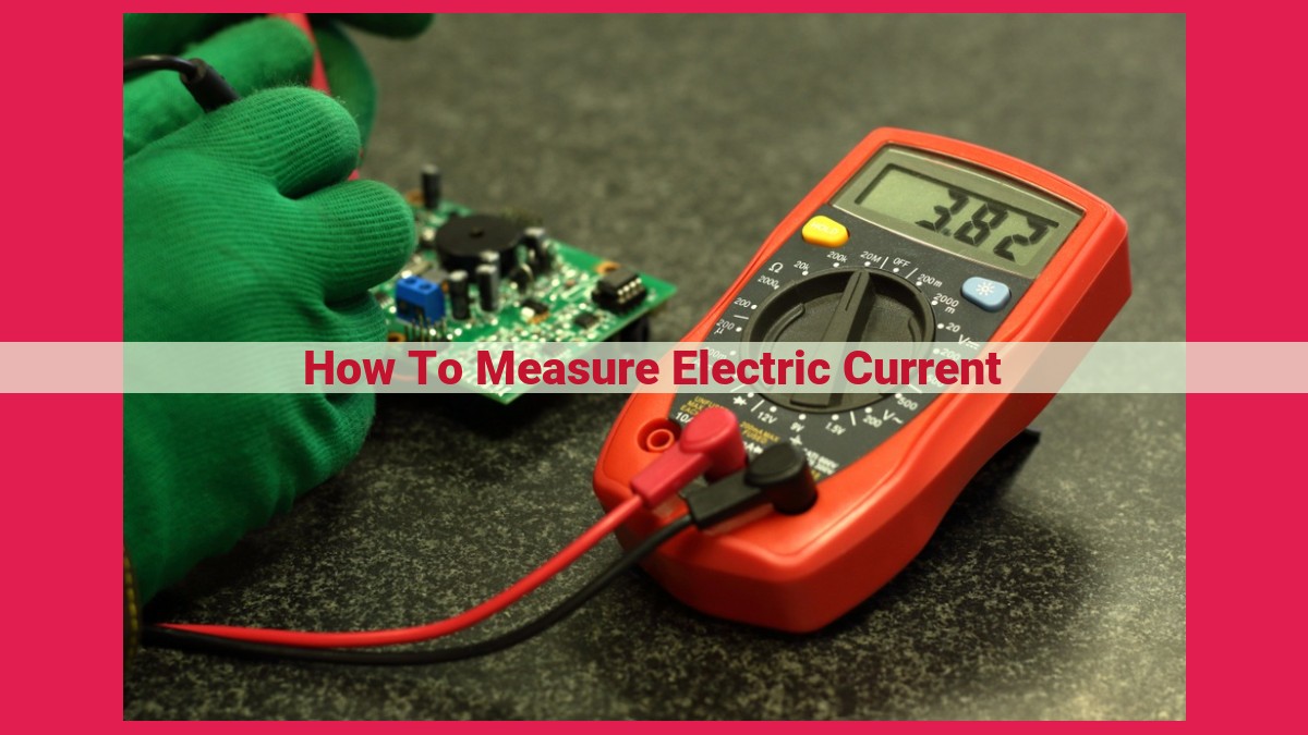
Measuring electric current involves using an ammeter, an instrument designed to measure current flow in a circuit. The ammeter is connected in series with the circuit, making it part of the current path. The ammeter’s display indicates the amount of current flowing through the circuit in amperes or milliamperes. The accuracy of the measurement depends on the range of the ammeter and its calibration. Proper connection of the ammeter is crucial to obtain accurate readings, and safety precautions should be followed while working with electrical circuits.
Understanding Electric Current: A Journey into the Flow of Electrons
In the realm of electricity, one of the most fundamental concepts is electric current, the movement of electrical charge within a closed circuit. Charge, represented by the symbol “q,” comes in two forms: positive and negative. Protons carry positive charge within the nucleus of an atom, while electrons, much lighter particles, carry negative charge and orbit the nucleus.
Conductors and insulators play crucial roles in electrical current. Conductors are materials, such as copper and aluminum, that allow electrons to flow through them easily. In contrast, insulators, such as rubber and plastic, impede the flow of electrons. This property of insulators makes them essential for preventing electrical shocks and short circuits.
Another key concept in understanding electric current is resistance. Resistance is a material’s ability to oppose the flow of electrons. It’s measured in ohms, and the higher the resistance, the more difficult it is for current to flow. Resistance plays a significant role in controlling the flow of current in circuits.
In summary, electric current, charge, conductors, and insulators are the building blocks of understanding electricity. By grasping these concepts, we can gain insight into the fundamental principles that govern the flow of electrons in our circuits.
Measuring Current: Unraveling the Secrets with Ammeters
What’s an Ammeter?
When it comes to understanding electrical circuits, current is a critical concept. And measuring current accurately is essential for troubleshooting, designing circuits, and ensuring safety. Meet the ammeter, an indispensable tool that allows us to quantify the flow of charge through a conductor.
Amp Units: A Tale of Magnitudes
Ammeters measure current in amperes, the metric unit of electrical current. To make sense of various magnitudes, we have milliamperes (mA) for smaller currents and microamperes (µA) for even tinier ones. Remember, 1 ampere equals 1000 milliamperes or 1,000,000 microamperes!
How Ammeters Work: A Peek Inside
Ammeters rely on a principle called the galvanometer. Essentially, when a current flows through a coil suspended in a magnetic field, it experiences a torque that turns the coil. The amount of deflection is proportional to the current flowing through the coil, providing a visual representation of the current magnitude.
Using Ammeters: Making the Connection
To measure current, an ammeter is connected in series with the circuit element you want to measure. This means the entire current flows through the ammeter, allowing it to sense and quantify the flow of charge.
Practical Considerations: Ensuring Accuracy and Safety
- Range Selection: Ammeters have specific ranges, so choose the one that matches the expected current magnitude. Exceeding the range can damage the ammeter.
- Series Connection: Always connect the ammeter in series with the circuit element to measure the current flowing through that element.
- Safety Precautions: Electrical circuits can be dangerous. Wear proper protective gear, follow safety protocols, and troubleshoot cautiously.
Resistance in Circuits: The Gatekeepers of Electrical Flow
The realm of electricity is a captivating dance of charged particles, and understanding how they move through circuits is crucial for unraveling the secrets of electrical engineering. Resistance plays a pivotal role in this choreography, acting as the gatekeeper that influences the flow of electric current.
Conductors and Insulators: A Tale of Two Materials
Imagine a highway where charged particles are cars. Conductors are like wide-open boulevards, allowing particles to zip through with ease. On the other hand, insulators are like narrow, winding roads, creating a labyrinth that severely hinders the movement of these microscopic vehicles.
Defining Resistance: The Obstacle Course Factor
Resistance is an inherent property of a material that opposes the flow of electric current. It’s like a barrier that makes it harder for the particles to move, resulting in a reduction in current. The higher the resistance, the greater the obstacle, and the less current flows. Resistance. is measured in ohms (Ω), so when you encounter a circuit with a high resistance, picture it as a formidable obstacle course for charged particles.
Ohm’s Law: The Golden Rule of Resistance
The relationship between resistance, current, and voltage is governed by Ohm’s Law. This law states that the current flowing through a conductor is directly proportional to the voltage applied across it and inversely proportional to the resistance. In other words, increasing voltage drives more current through a conductor, while increasing resistance impedes the flow.
Kirchhoff’s Current Law (KCL)
Imagine a junction in an electrical circuit, where multiple wires meet like a bustling crossroads. Just as traffic flows in and out of an intersection, so too does electrical current flow in and out of junctions.
Kirchhoff’s Current Law (KCL), named after the brilliant physicist Gustav Kirchhoff, is the guiding principle that governs this electrical traffic. It states that the total current flowing into a junction must equal the total current flowing out. In other words, the net current at a junction is zero.
This law is a fundamental principle of circuit analysis. It allows us to determine the currents flowing through different branches of a circuit, even when the circuit is complex and intricate.
To apply KCL, we simply add up the currents flowing into a junction and equate them to the sum of the currents flowing out. Currents flowing into the junction are considered positive, while currents flowing out are considered negative.
For example, consider a junction with three wires connected to it. If a current of 2 amps is flowing into the junction from one wire, a current of 1 amp is flowing out from another wire, and a current of 3 amps is flowing out from the third wire, then KCL tells us that:
2 amps + 1 amps = 3 amps
This equation holds true because the net current at the junction is zero.
Kirchhoff’s Current Law is an essential tool for understanding and designing electrical circuits. It allows us to predict the behavior of currents in a circuit and ensure that the circuit functions properly.
Ohm’s Law
- Explore the relationship between resistance, voltage, and current.
- Present Ohm’s Law formula and its applications.
Ohm’s Law: The Key to Understanding Circuit Behavior
In the world of electricity, understanding the relationship between voltage, current, and resistance is crucial. This intricate dance is governed by a fundamental principle known as Ohm’s Law. Named after the brilliant physicist Georg Ohm, this law provides a mathematical framework to analyze and predict the behavior of electrical circuits.
The Ohm’s Law Formula
The heart of Ohm’s Law lies in a simple equation:
Voltage (V) = Current (I) × Resistance (R)
This formula reveals that voltage (the driving force behind electrical flow) is directly proportional to both current (the flow of electrical charge) and resistance (the opposition to current flow).
Applications of Ohm’s Law
Ohm’s Law has countless applications in electrical engineering and electronics. It finds use in:
- Circuit analysis: Determining the voltage, current, or resistance in a circuit based on known values.
- Designing electronic devices: Calculating the appropriate resistance to achieve desired current or voltage levels.
- Troubleshooting electrical circuits: Identifying faults or malfunctions by measuring voltage, current, and resistance.
Unveiling the Effects of Voltage, Current, and Resistance
Ohm’s Law allows us to explore the interplay between these three factors. For instance, increasing the voltage across a fixed resistance results in an increase in current. Conversely, increasing the resistance while keeping the voltage constant leads to a decrease in current.
Resistance plays a pivotal role in determining the current flow in a circuit. A low resistance allows electrons to flow easily, resulting in high current. On the contrary, high resistance impedes electron flow, leading to a smaller current.
Ohm’s Law is an indispensable tool for comprehending electrical circuits and their behavior. By understanding the relationships between voltage, current, and resistance, engineers, technicians, and hobbyists alike can design, analyze, and troubleshoot electrical systems with confidence.
Multi-Channel Ammeters: Empowering Engineers with Simultaneous Current Monitoring
In the intricate world of electrical engineering, meticulous current monitoring is crucial. Multi-channel ammeters have emerged as game-changers in this realm, empowering engineers to effortlessly measure current across multiple channels concurrently. These advanced devices have transformed the way electrical systems are analyzed, troubleshooted, and optimized.
Imagine a scenario where you need to monitor the current flowing through several branches of a complex electrical circuit. Traditional ammeters would require you to switch between channels manually, a tedious and time-consuming process. Multi-channel ammeters, on the other hand, alleviate this challenge by providing multiple measurement channels within a single instrument. This simultaneous monitoring capability not only saves precious time but also ensures consistent accuracy across all channels.
The advantages of multi-channel ammeters extend beyond their time-saving capabilities. By eliminating the need for manual channel switching, these devices minimize human error and improve measurement consistency. Their compact design allows for easy integration into complex setups, making them ideal for applications where space is a constraint. Furthermore, multi-channel ammeters typically offer advanced features such as data logging, waveform analysis, and remote connectivity, enhancing the versatility and efficiency of electro-technical investigations.
However, it is important to acknowledge that multi-channel ammeters may come with certain trade-offs compared to dedicated single-channel ammeters. Cost can be a factor, as multi-channel devices generally have a higher price point. Additionally, bandwidth limitations may apply, meaning that the maximum frequency of the signals that can be measured may be restricted.
For applications requiring high-speed current monitoring, dedicated single-channel ammeters may be a better choice. However, when simultaneous measurement across multiple channels is a priority, multi-channel ammeters prove to be invaluable tools. These devices empower engineers with increased efficiency, accuracy, and convenience, making complex electrical system analysis a breeze.
Practical Considerations for Current Measurement
When measuring current, there are several practical considerations to keep in mind to ensure accuracy and safety.
Range Selection and Accuracy
Ammeters, devices used to measure current, have specific ranges they can measure. Selecting the appropriate range is crucial to avoid overloading the ammeter or getting inaccurate readings. For better accuracy, it’s recommended to choose a range where the expected current value falls within the middle of the range. This minimizes measurement errors and provides reliable results.
Proper Series Connection
Ammeters must be connected in series with the circuit to accurately measure current. This arrangement allows the current to flow through the ammeter, providing a direct measurement of its magnitude. Incorrect connections, such as connecting the ammeter in parallel, will result in inaccurate readings and potentially damage the ammeter.
Safety Precautions
Current measurement involves working with electrical circuits, so safety precautions are paramount. Ensure that the circuit is de-energized before connecting or disconnecting the ammeter. Use insulated tools and avoid touching live wires or terminals to prevent electrical shocks. Always follow proper electrical safety guidelines to minimize risks.
Troubleshooting Tips
If you encounter any issues during current measurement, there are some common troubleshooting tips to consider:
- Check the battery: A low or dead battery in the ammeter can lead to inaccurate readings. Replace the battery if necessary.
- Clean the connections: Loose or dirty connections between the ammeter and the circuit can cause poor readings. Secure connections and clean any dirt or corrosion.
- Inspect the ammeter: If the ammeter consistently gives incorrect readings, it may be faulty. Check if there is any physical damage or internal issues. Calibrate or replace the ammeter as needed.
