Mastering Potential Dividers: A Comprehensive Guide To Voltage Division Techniques
A potential divider is a voltage divider circuit that uses resistors to create a voltage divider network. It divides an input voltage into two or more output voltages with different magnitudes. The output voltage is proportional to the ratio of the resistances in the network, and the resistors are selected to achieve the desired voltage division. Potential dividers are used in various applications, including voltage regulation, signal conditioning, bias networks, and feedback networks.
Understanding Potential Dividers: A Guide for Beginners
In the realm of electronics, precision and control are paramount. To harness the power of electricity, we often encounter the need to adjust, divide, or fine-tune voltages. Enter the potential divider, an ingenious circuit element that empowers us to mold voltage signals to our desires. Let’s unravel the secrets of this versatile tool and explore its applications.
Defining Potential Dividers:
A potential divider is an electrical circuit element that, as its name suggests, divides the potential (voltage) across two resistors connected in series. Its primary purpose is to reduce or regulate voltage levels, enabling finer control over electronic circuits.
Operation Principles:
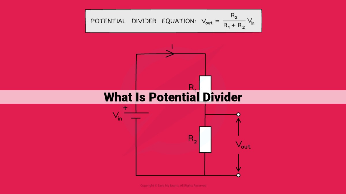
Potential dividers operate on the fundamental principles of Ohm’s Law and voltage division. When two resistors, R1 and R2, are connected in series, the total resistance of the circuit becomes the sum of their individual resistances. As current flows through the resistors, a voltage drop occurs across each resistor proportional to its resistance.
The output voltage (Vout) at the junction between the resistors is then given by the following formula:
Vout = (R2 / (R1 + R2)) * Vin
where Vin is the input voltage applied to the circuit.
Construction and Components:
Potential dividers typically consist of two resistors, R1 and R2, connected in series. The selection of resistors is crucial to achieve the desired output voltage. Higher resistance values result in a lower output voltage, while lower resistance values yield a higher output voltage. The resistors should also be stable and have a tolerance within acceptable limits to ensure accuracy.
Applications of Potential Dividers:
Potential dividers have numerous applications in electronics, including:
- Voltage adjustment and regulation: Fine-tuning voltage levels for various electronic circuits, such as sensors and amplifiers.
- Sensor signal conditioning: Scaling sensor output signals to match the input range of data acquisition systems.
- Level shifting: Adjusting voltage levels to match the requirements of different circuit components.
- Bias networks: Providing bias voltage for transistors and other semiconductor devices.
- Feedback networks: Controlling the gain and stability of amplifiers and other circuits.
Advantages and Limitations:
Potential dividers offer several advantages, including:
- Simplicity and cost-effectiveness: Easy to design and implement, requiring only a few passive components.
- Accuracy and stability: Provides stable and predictable output voltages when using high-quality resistors.
However, potential dividers also have limitations:
- Power dissipation: Resistive circuits consume power, which can be a concern in high-power applications.
- Loading effects: Output voltage can be affected by the input impedance of the subsequent circuit (loading).
Construction and Components of a Potential Divider
Potential dividers are essential components in electronics, used to adjust and regulate voltages. Their construction involves carefully selecting resistors and designing the network for specific applications.
Types of Resistors
Resistors used in potential dividers come in various types, each with unique characteristics. Carbon composition resistors are common and inexpensive, but their resistance can vary with temperature and voltage. Metal film resistors offer higher accuracy and stability, making them suitable for precise applications. Ceramic resistors are also reliable and can withstand high temperatures.
Selection Considerations
When choosing resistors for a potential divider, consider the following:
* Resistance Value: The resistors’ values determine the voltage division ratio.
* Power Rating: The power rating indicates how much power the resistor can dissipate without overheating. Choose resistors with a power rating higher than the expected power dissipation.
* Tolerance: The tolerance specifies the allowable deviation from the nominal resistance value. For precise applications, use resistors with low tolerance.
Network Design and Connection
The resistors in a potential divider are typically connected in series, with the output voltage taken from the junction between them. The design of the network depends on the desired voltage division ratio.
- Series Connection: Resistors are connected end-to-end in a single series path.
- Parallel Connection: Resistors are connected in parallel to provide multiple paths for current flow.
- Combination of Series and Parallel: Complex networks can combine series and parallel connections to achieve specific voltage division ratios.
The proper connection of resistors ensures that the voltage is divided correctly across the network. Soldered or crimped connections are typically used for permanent connections, while breadboards allow for temporary or experimental setups.
The construction of a potential divider involves selecting appropriate resistors and designing the network to meet specific requirements. Understanding the types of resistors, selection considerations, and network design principles is crucial for creating efficient and reliable potential dividers in electronic circuits.
Understanding the Potential Divider Formula and Calculations
In the realm of electronics, potential dividers play a crucial role in voltage adjustments and regulation. Comprehending the underlying formula is essential for using these circuits effectively. So, let’s delve into the world of potential divider calculations!
The Formula Unleashed
The output voltage of a potential divider, denoted as Vout, is determined by the ratio of the resistors involved. The formula is:
Vout = (R2 / (R1 + R2)) * Vin
where:
- Vout is the output voltage
- R1 is the resistance of the first resistor
- R2 is the resistance of the second resistor
- Vin is the input voltage
Decoding the Variables
The variables in the formula represent specific characteristics of the circuit:
- R1 and R2 determine the voltage division ratio.
- R1 and R2 should be chosen carefully to ensure the desired output voltage.
- Vin is the voltage applied to the input of the potential divider.
Example Calculation: A Step-by-Step Journey
Let’s illustrate the formula with an example. Suppose you have a potential divider with R1 = 10kΩ and R2 = 5kΩ. The input voltage is 12V. What’s the output voltage?
- Plug in the values: Vout = (5kΩ / (10kΩ + 5kΩ)) * 12V
- Simplify the denominator: Vout = (5kΩ / 15kΩ) * 12V
- Calculate the division ratio: Vout = (1/3) * 12V
- Find the output voltage: Vout = 4V
Therefore, the output voltage of the potential divider is 4V.
Derivation and Principle of Operation of a Potential Divider
Understanding Voltage Division
A potential divider, essentially, is a voltage sharing circuit. It harnesses the concept of voltage division, where the applied voltage is distributed across multiple resistors in a series connection. This voltage distribution forms the basis of the potential divider’s operation.
Derivation of the Formula
The potential divider formula, Vout = Vin * (R2 / (R1 + R2)), can be derived using Ohm’s law and the principle of voltage division. Ohm’s law states that the voltage drop across a resistor is directly proportional to the current flowing through it.
In a potential divider circuit, the current flowing through both resistors is the same. Let’s denote the current as ‘I’. Using Ohm’s law, the voltage drop across R1 can be expressed as VR1 = I * R1, and the voltage drop across R2 as VR2 = I * R2.
The principle of voltage division states that the voltage across a resistor in a series connection is directly proportional to its resistance. Thus, VR1 / Vin = R1 / (R1 + R2) and VR2 / Vin = R2 / (R1 + R2).
Combining these equations, we get:
VR2 / Vin = Vout / Vin = R2 / (R1 + R2)
This equation is the potential divider formula, which allows us to calculate the output voltage based on the input voltage and the resistance values.
Distribution of Voltage
In a potential divider circuit, the voltage is distributed across the resistors in proportion to their resistances. The resistor with the higher resistance has a larger voltage drop, while the resistor with the lower resistance has a smaller voltage drop.
This voltage distribution is crucial, as it allows us to adjust the output voltage by changing the resistance values. By selecting appropriate resistor values, we can create a voltage divider that outputs a desired voltage level.
Applications of Potential Dividers
- List and describe the various applications of potential dividers in electronics, such as:
- Voltage adjustment and regulation
- Sensor signal conditioning
- Level shifting
- Bias networks
- Feedback networks
Applications of Potential Dividers in Electronics
In the realm of electronics, potential dividers play a pivotal role in a wide array of applications. These simple yet versatile circuits offer a cost-effective and reliable means of voltage adjustment, regulation, and signal conditioning.
Voltage Adjustment and Regulation
One of the most common uses of potential dividers is to adjust or regulate voltage levels. By varying the resistance of the resistors in the network, the output voltage can be precisely controlled. This feature makes potential dividers ideal for powering sensitive electronic components or creating stable reference voltages.
Sensor Signal Conditioning
Potential dividers are also commonly used in sensor signal conditioning. Many sensors produce output signals that are non-linear or incompatible with the input range of subsequent circuitry. By using a potential divider, the sensor signal can be scaled or adjusted to match the desired input range, ensuring accurate and reliable data acquisition.
Level Shifting
Level shifting is another important application of potential dividers. In digital circuits, different logic families operate at different voltage levels. Potential dividers can be used to convert voltage levels from one logic family to another, allowing interfacing between different components and ensuring compatibility.
Bias Networks
In amplifier circuits, potential dividers are often used to create bias networks. These networks provide a stable reference voltage or current that sets the operating point of the amplifier. By carefully selecting the resistance values, the bias network can optimize the amplifier’s gain, linearity, and stability.
Feedback Networks
Potential dividers also play a crucial role in creating feedback networks. In operational amplifier circuits, feedback is used to control the amplifier’s gain and frequency response. Potential dividers in these feedback networks adjust the amount of feedback and determine the overall behavior of the amplifier.
Advantages of Potential Dividers
The simplicity and cost-effectiveness of potential dividers make them a popular choice for a wide range of applications. Their design consists of just a few resistors, making them easy to implement and inexpensive to manufacture. This simplicity also contributes to their reliability and maintainability.
Another advantage of potential dividers is their accuracy and stability. When constructed with high-quality resistors, potential dividers can provide precise and consistent voltage division over a wide range of operating conditions. This stability is crucial for applications where precise voltage levels are essential, such as signal conditioning and calibration circuits.
Limitations of Potential Dividers
Despite their advantages, potential dividers have certain limitations that must be considered. One limitation is power dissipation. When a potential divider draws current from a source, power is dissipated in the resistors. This can become a concern if the current flow is high or if the resistors have low power ratings. This power dissipation can lead to heating and potential damage to the resistors.
Another limitation of potential dividers is loading effects. The output voltage of a potential divider is affected by the impedance of the load connected to it. If the load impedance is low, it can draw more current from the divider, which can alter the output voltage. To minimize loading effects, it’s important to ensure that the load impedance is high compared to the resistance of the potential divider.
Finally, potential dividers can exhibit non-linear behavior under certain conditions. This can occur when the resistance of the resistors changes due to factors such as temperature variations or aging. As a result, the output voltage may not always be perfectly proportional to the input voltage, which can limit the accuracy of the divider.
