Mastering Bode Plots: A Comprehensive Guide With Seo Optimization

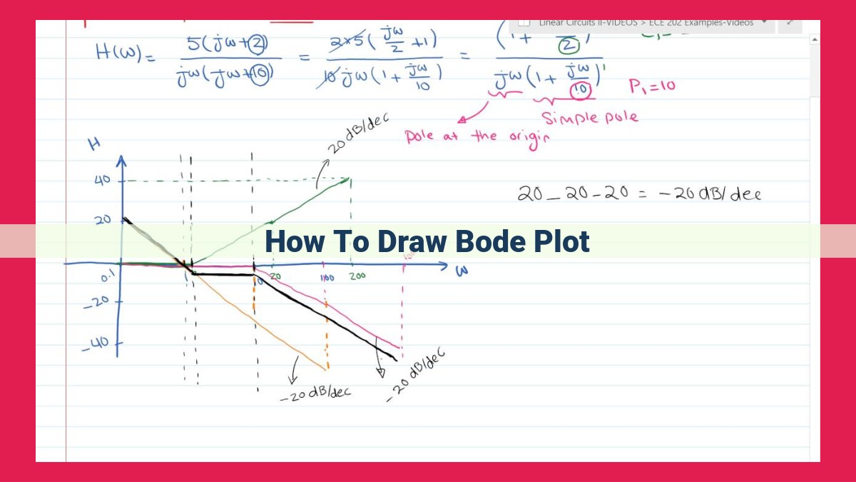
To draw a Bode plot, first understand the concepts of corner and break frequencies, log frequency scale, and asymptotic approximation. Draw the magnitude response plot by plotting gain (decibels) as a function of log frequency. Then, draw the phase response plot by plotting phase shift as a function of log frequency. Use asymptotic approximations to simplify the plots and identify dominant poles and zeros. Finally, consider the transfer function and its impact on the Bode plot.
Bode Plots: Unveiling the Secrets of Frequency Response
In the realm of frequency response analysis, Bode plots emerge as indispensable tools, unlocking the secrets of how systems behave at different frequencies. These plots provide invaluable insights into the characteristics of circuits, filters, and other systems, enabling engineers to optimize design and performance.
Defining Bode Plots
Bode plots are graphical representations that depict the frequency response of a system. They encompass two distinct plots: magnitude response and phase response. The magnitude response reveals how the system’s output amplitude varies with frequency, while the phase response indicates the phase shift between the input and output signals.
Significance in Frequency Response Analysis
Bode plots hold immense significance in frequency response analysis. They provide a comprehensive understanding of a system’s behavior across a wide frequency range. This information is crucial for designing amplifiers, filters, and control systems with specific performance requirements, such as stability, bandwidth, and gain characteristics.
Unveiling Bode Plots: A Journey Through Frequency Response Analysis
In the realm of electrical engineering, the analysis of frequency response plays a crucial role in understanding the behavior of circuits and systems. Among the many tools used for this purpose, Bode plots stand out as a powerful and versatile technique. In this comprehensive guide, we will embark on a storytelling journey to unravel the key concepts of Bode plots and their applications in frequency response analysis.
Understanding the Language of Bode Plots
Frequency response analysis involves studying how a system’s output responds to variations in the frequency of its input signal. Bode plots present this information in a graphical format, using two separate plots: the magnitude response and the phase response.
The magnitude response displays how the gain or amplitude of the output signal changes with frequency. It is typically plotted in decibels (dB), which is a logarithmic scale that compresses a wide range of values into a manageable graph.
The phase response shows how the time delay between the input and output signals varies with frequency. It is plotted in degrees and provides insights into the system’s phase shift characteristics.
Key Concepts: A Deeper Dive
To fully grasp the concepts behind Bode plots, we need to delve into three key elements:
Corner Frequency (f_c): This frequency marks the point where the magnitude response begins to decay at a rate of 20 dB per decade. It arises from the presence of poles in the system’s transfer function, which are complex numbers that can introduce phase shifts and attenuation.
Break Frequency (f_0): This frequency corresponds to the point where the phase shift in the system reaches -90 degrees. It signifies the dominant pole or zero in the transfer function, which contributes significantly to the system’s phase characteristics.
Log Frequency Scale: This scale offers a convenient way to visualize a wide range of frequencies. It compresses the frequency axis so that equal distances represent equal percentage changes in frequency, enabling a comprehensive view of the system’s behavior over a broad spectrum.
The Essence of Magnitude Response: Unraveling Bode Plots
In the realm of frequency response analysis, Bode plots stand as indispensable tools, painting a revealing picture of how systems behave across different frequencies. These plots shed light on the magnitude response of a system, providing insights into its gain and attenuation characteristics.
Defining Magnitude Response:
Magnitude response, often measured in decibels (dB), describes how much a system amplifies or attenuates a signal at a given frequency. A positive dB value indicates amplification (gain), while a negative dB value signifies attenuation (loss).
Interpreting Gain on Bode Plots:
On a Bode plot, the magnitude response is typically plotted on a logarithmic scale, allowing for a comprehensive view of gain over a wide frequency range. Horizontal lines represent constant gain, while sloped lines indicate rate of gain change.
Asymptotic Approximation:
To simplify Bode plot analysis, asymptotic approximations are employed. These approximations provide straight-line approximations of the magnitude response, making it easier to estimate gain and identify important frequencies. The most common asymptotic approximations are 0 dB (flat line) and -20 dB/decade (sloped line with a -20 dB gain change for every tenfold frequency increase).
Practical Significance:
Magnitude response plays a crucial role in system design and troubleshooting. By analyzing the magnitude response of a system, engineers can determine its gain characteristics, frequency response, and stability. For instance, in audio systems, magnitude response determines the system’s loudness and equalization.
Example:
Consider a Bode plot with a magnitude response that initially increases by 20 dB/decade (sloped line) and then flattens out at 0 dB. This suggests that the system amplifies the signal at low frequencies and then reaches a constant gain at higher frequencies.
Understanding Phase Response in Bode Plots
In the realm of frequency response analysis, we encounter Bode plots, a powerful tool that unveils the intricacies of a system’s behavior at various frequencies. One crucial aspect of Bode plots is the phase response, which provides insights into the system’s temporal behavior.
Phase Response: A Tale of Time Delays
Phase response plots illustrate how the output signal of a system lags or leads the input signal as frequency varies. This lag is expressed in degrees or radians and is directly related to the locations of the system’s poles in the complex frequency plane.
Poles and Phase Shift
As frequencies approach the corner frequency of a pole, the phase response undergoes significant changes. A pole in the left half-plane (LHP) introduces a phase lag, while a pole in the right half-plane (RHP) results in a phase lead.
Frequency Variations and Phase Shift
At low frequencies, the system’s output can closely track the input, resulting in a near-zero phase shift. As the frequency increases, the phase shift becomes more pronounced, particularly near the corner frequencies of dominant poles.
Interpreting Phase Plots
Bode plots provide a visual representation of the phase response, allowing engineers to analyze the system’s stability, time delays, and potential resonances. By understanding the relationship between poles and phase shift, we gain a deeper understanding of a system’s dynamic behavior.
Asymptotic Approximation: Simplifying Bode Plots
Delving deeper into the analysis of Bode plots, we encounter the concept of asymptotic approximation. It’s a handy technique that allows us to simplify the complex shapes of Bode plots and make them more manageable.
The idea behind asymptotic approximation is to break down the Bode plot into simpler linear segments, each of which approximates a particular region of the plot. We use big-O notation to quantify this approximation, where O(x) represents the order of growth of the function as x approaches infinity.
For instance, in the magnitude response, we might approximate a segment with a slope of 20 dB/decade as O(f^2). This means that as frequency increases, the magnitude response grows in proportion to the square of the frequency.
In the phase response, we might approximate a segment with a slope of -90 degrees/decade as O(1/f). This indicates that as frequency increases, the phase shift decreases in proportion to the reciprocal of the frequency.
Identifying the dominant poles and zeros in a Bode plot is crucial for this approximation. These are the poles and zeros that have the most significant impact on the shape of the plot. By focusing on the dominant poles and zeros, we can isolate the key features of the plot and simplify our analysis.
Asymptotic approximation is an essential tool in Bode plot analysis, allowing us to simplify complex plots and gain a clearer understanding of the frequency response of a system. It’s a technique that makes Bode plots more accessible and practical for design and analysis tasks.
Unveiling Bode Plots: A Comprehensive Guide to Frequency Response Analysis
Bode plots are graphical representations of the frequency response of a system. They allow engineers to visualize how a system responds to input signals of varying frequencies. This information is crucial for designing and analyzing various electronic and control systems.
Understanding Key Concepts
Bode plots have two main characteristics:
- Magnitude response: Shows how the gain of a system changes with frequency.
- Phase response: Shows how the time delay of a system changes with frequency.
Both magnitude and phase responses are plotted on a logarithmic frequency scale to cover a wide range of frequencies.
Magnitude Response: Bode Plot
The magnitude response of a system is expressed in decibels (dB). It indicates how the amplitude of the output signal varies relative to the input signal. Bode plots use straight lines called asymptotes to approximate the response. Asymptotes have slopes that correspond to the poles and zeros of the system’s transfer function.
Asymptotic Approximation
Asymptotic approximations simplify the analysis of Bode plots. They use big-O notation to describe how the response eventually behaves as frequency increases or decreases. This approximation helps identify the dominant poles and zeros that have the most significant impact on the system’s response.
Transfer Function
The transfer function is a mathematical equation that describes the relationship between the input and output signals of a system. It contains poles and zeros, which are complex numbers that determine the system’s frequency response. The transfer function is essential for constructing Bode plots and understanding the system’s behavior.
Nyquist Plot
- Overview of Nyquist plots and their relationship to Bode plots.
- Interpretation of stability and gain margin from Nyquist plots.
Bode Plots: Unlocking the Secrets of Frequency Response
Welcome to the fascinating world of Bode plots, essential tools that unveil the frequency-dependent behavior of systems. Join us as we embark on an adventure through this invaluable analytical technique.
Understanding the Fundamentals
At the core of Bode plots lie two key concepts: corner frequency (f_c) and break frequency (f_0). Corner frequency marks the transition from low-frequency to high-frequency regions, while break frequency signifies the point where phase shift begins to accumulate. We’ll visualize these frequencies using a logarithmic frequency scale, allowing us to effortlessly traverse vast frequency ranges.
Magnitude Response: Plotting the Power
The magnitude response plot reveals the gain (decibels) of a system across frequencies. It illustrates how the system amplifies or attenuates input signals. This plot employs asymptotic approximations to simplify analysis, representing the magnitude response as a series of straight lines.
Phase Response: Exploring the Time Shift
In contrast, the phase response plot depicts the time shift between input and output signals. It helps identify poles in the system, which contribute to abrupt phase changes. By analyzing the phase response, we can gain insights into the system’s stability and resonance characteristics.
Asymptotic Approximation: Simplifying Complexity
Recognizing that Bode plots approximate real-world systems, we utilize asymptotic approximations to simplify complex transfer functions. These approximations, expressed using big-O notation, help identify dominant poles and zeros, enabling us to capture the system’s primary characteristics.
Transfer Function: The Blueprint of Frequency Response
The transfer function, a mathematical equation, defines the relationship between input and output signals. It contains poles and zeros that dictate the system’s frequency response. By analyzing the transfer function, we can predict how the system will behave at various frequencies.
Nyquist Plot: Stability and Gain Margin Unveiled
Finally, let’s explore the intriguing Nyquist plot, an extension of the Bode plot. It provides a visual representation of the transfer function, complete with poles and zeros plotted in the complex plane. The Nyquist plot reveals the system’s stability and helps determine gain margin and phase margin, crucial parameters for control system design.
In the realm of frequency analysis, Bode plots shine as indispensable tools, empowering us to dissect and comprehend system behavior. Embrace their power to unlock the secrets of frequency response and delve into a world of engineering marvels.


